Showing posts with label Useful Circuits. Show all posts

Monday, June 10, 2024

Over Current Protection at Output Stage/ Pins


This circuit helps to limit the output current less than 20mA which can be sense and set by R1 & R8. It also disconnects I/O when the output shorts to positive high voltage or negative high voltage by limiting the current.

The diode, D1at the output and 5V0 pin is used to suppress the kick-back voltage from an inductive load that is excited when the drivers are turned off (stop sinking) and the stored energy in the coils causes a reverse current to flow into the coil supply through the kick-back diode

How to use MOSFET for Hide Side Switching


This circuit can be used for high voltage (100V max) and high current (33.6A) high side load switching. P-Ch MOSFET,Q1 has been chosen as it as very low ON-Resistance. For high voltage switching, R1 and R2 help to limit the VGS not to exceed VGS max. Another option is adding Zener diode across Gate and Source. N-CH MOSFET, ON/OFF control is driven by small signal N-CH MOSFET, Q2. When ON/OFF CTRL is low Q2 is OFF. When it is high, Q2 activate lowering P-CH gate voltage via R2 which also limits the current.

Friday, June 7, 2024

Overvoltage Protection


This circuit monitor VIN and protect the output voltage by a series connected transistor Q14. During over voltage condition Q14 B is turn on which cause Q14A to disconnect output to VIN. Desired overvoltage limit is set by D10 plus VBE of Q14. For example, if the required cutout voltage is 12V, Zener voltage of D10 has to be 12-0.6= 11.4 V.


Monday, May 16, 2022

CAN-BUS Termination and Protection

 A properly terminated CAN bus is terminated at each end with the characteristic impedance of the cable, this is typically 120Ω on each end for a 60Ω load on the CAN driver. The 60Ω–60Ω split termination is preferred to reduce high-frequency noise and common-mode drift. Usually, 60R resistor is not cost effective and a choice of 60.4R with 1% tolerance is better.


If we are using CAN-BUS for long distance for more than 50m, it is advised to reduce the bitrate to minimize an errors and signal distortions.

The maximum possible CAN Bitrate depends on the total CAN bus cable length: 

- 1 Mbit/s: max. 40 m

- 500 kBit/s: max. 100 m

- 125 kBit/s: max. 500 m  

To enhance CAN Bus reliability, communication BUS varistor can be added near next to the connectors.

If the device is intended to be used in harsh environment and required isolation due to ground potential difference between subsystems, Galvanic isolation barrier can be placed between CAN BUS transceiver and MCU. It is also important to use isolated DC-DC power supply for transceiver.

Thursday, May 12, 2022

Simple Capacitive Touch Sensor Controller

 If you need a simple capacitive touch sensor to our project, Microchip's CAP1203 is a good choice. It is a multiple channel capacitive touch sensor controller with calibrated to compensate for system parasitic capacitance and automatically recalibrated to compensate for gradual environmental changes. The best thing about this chip is low power consumption at deep sleep mode. It can be used as a touch slider and worked under 6 mm thickness of plastic or wood or almost any materials.


PCB pad Design as below.


Sparkfun has remade module to try.


Thursday, May 5, 2022

Open LED Protection for LED Strings

 LEDs are fragile solid-state devices. An LED is essentially a diode, structured as a P-N junction that emits light when forward biased. One of the major causes of an electrical open in an LED is thermomechanical stress on the wire bonds. Other causes of LED open circuits are electrostatic discharge (ESD) events or surges induced by nearby lightning events. These threats are especially high in outdoor applications. Devices such as MOVs, fuses, and TVS diodes are essential components of a circuit protection strategy, because they can prevent transients and surges from damaging delicate LEDs. However, none of these traditional circuit protection devices can prevent an entire string of LEDs from going out if a single LED fails.  


An open LED protector is  can be connected in parallel with each LED in a string; it will shunt current around an openfailed LED to keep the rest of the string lit. When LED fails open-Circuit, the open LED protector goes into conduction, limiting its voltage drop to about 1.3V and keeping the rest of the string operating.


Voltage-Tracking LDO With 4-mV Tracking Tolerance

 Voltage-tracking low dropout regulator (LDO) is widely used in automotive off-board sensors and small current off-board modules for its off-board protection and high voltage-tracking accuracy advantages.The output of the device is accurately regulated by a reference voltage at the ADJ pin.

To get accurate sensor readings, power supply is required to be stable and accurate. To provide an accurate power supply to the off-board modules, this device offers a 4-mV ultralow tracking
tolerance between the ADJ and FB pins across temperature. Recommend PCB layout sample by TI as below.


Tuesday, September 21, 2021

Voltage controlled Current Source Circuit


This circuit control the output current flow effectively. Reference voltage V1 can be set to desire output current, for instance V1=700 mV is setting output current to 670 mA.

Friday, July 17, 2020

Low cost temperature sensor


Low cost temperature sensor can be achieved by using diode or transistor (by shorting Base and Collector). When constant current passes through the base-emitter junction it produces a voltage between the base and emitter (Vbe) that is a linear function of the absolute temperature. 
The overall forward voltage drop has a temperature coefficient of approximately 2 mV/°C. The semiconductor junction sensor’s voltage versus temperature is much more linear than that of a thermocouple or resistive temperature device (RTD). 

Friday, April 24, 2020

Implementing Ship Mode to Your Product

As the presence of global manufacturing and distribution increases, many original equipment manufacturers are looking for creative ways to extend battery life during shipping and shelf life at big-box warehouses. Keeping the battery sufficiently charged during shipment enables a consistent out-of-box experience for the end-user. A solution that has gained popularity is the use of a ship mode feature that keeps devices in a low-power state during shipment and while on the shelf. Here is my solution using a load switch from TI, TPS22915B.
This is how the circuit works. Before the button is pressed, the solution is in ship mode, meaning that the system is not powered and theTPS22915B load switch is turned off. When the button is pressed, the voltage from the battery is passed through the PMOS to the ON pin of the TPS22915B. The voltage enables the TPS22915B, brings VOUT high, turns off the PMOS, and powers the system. The ON pin is pulled up to VOUT, which keeps the load switch enabled even after the button is released.

Friday, February 21, 2020

Wednesday, November 21, 2018

AAA Battery Protection with Wrong Polarity LED Indicator

This simple circuit will protect AA or AAA battery from wrong polarity connection to your device. If the battery is connected in opposite way, D1 will conduct and PTC Fuse will break the circuit. Wrong polarity indicator, LED 1 will be turned on at the same time.

Thursday, June 7, 2018

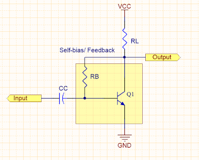
A Basic Transistor Amplifier with self-bias

This circuit will amplified the input signal with self-bias or feedback which can prevent amplitude distortion. However, it has two small drawbacks. It is only partially effective and, therefore, is only used where moderate changes in ambient temperature are expected.It reduces amplification since the signal on the collector also effects the base voltage. This is because the collector and base signals for this particular amplifier configuration are 180 degrees out of phase (opposite in polarity) and the part of the collector signal that is fed back to the base cancels some of the input signal. This process of returning a part of the output back to its input is known as DEGENERATION or NEGATIVE FEEDBACK. Sometimes degeneration is desired to prevent amplitude distortion (an output signal that fails to follow the input exactly) and self-bias may be used for this purpose.

Wednesday, June 6, 2018

Common Mode and Differential Mode Filters to limit EMI Issues

This EMI filter include common-mode filter and differential mode filter. Generally Differential mode filter filters noise less than 30MHz and Common mode filter filers noise from 30 MHz to 100 MHz. Both filter have an effect on the entire frequency where EMI needs limiting.

Thursday, May 24, 2018

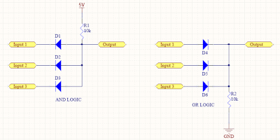
Simple Logic Gates using Diodes


Diodes can be used for implementing simple logic gates such as AND or OR combinations. For AND gate, all inputs must be tie to high, 5V for the output logic high. For OR gate, the output is high if any input(s) are high.

Thursday, May 10, 2018

Emergency Phone Charger From 3 x AA Battery with output Protection


Three AA batteries (3 x 1.5V) is using as emergency power source for mobile device or phone charging. Output current is limited to 0.5A and protected from out short circuit or high current drawn from the batteries.

Tuesday, April 17, 2018

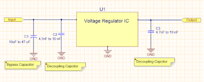
Bypass & Decoupling Caps Selection for Voltage Regulators

Bypass Capacitors
The main function of the bypass capacitor is to create an AC shunt to remove undesirable energy from  entering susceptible areas.  The bypass capacitor is acting as a high frequency bypass source to reduce the transient circuit demand on the power supply unit. Usually, aluminium or tantalum capacitor is a good choice for bypass capacitors, its value depends on the transient current demand on the PCB, but it is usually in the range of 10 to 47 uF. Larger values are required on the PCB with a large number of integrated circuits, fast switching circuits, and PSUs and having long leads to PCB.

Decoupling Capacitors
During active device switching, the high frequency switching noise created is distributed along the power supply lines. The main function of the decoupling is to provide localised source of DC power for the active devices, thus reducing switching noise propagating across the board and decoupling the noise to ground.

Ideally, the bypass and decoupling should be placed as close as possible to the power supply inlet to help filter high frequency noises. The value of decouupling capacitor is approximately 1/100 or 1/1000 of the bypass capacitor. For better EMC performance, decoupling capacitors should be placed as close as possible to each IC, because trace impedance will reduce the effectiveness of decoupling function.

Creamic capacitors are usually selected for decoupling; choosing the value depends on the rise and fall times of the fastest signal. For example, with a 33 MHz clock frequency, use 4.7nF to 100nF, with a 100 MHz clock frequency use 10nF.

Apart from the capacitance value when choosing the decoupling capacitor, the low ESR of the capacitor also affects its decoupling capabilities. For decoupling, it is preferable to choose capacitors with a ESR value less than 1 ohm.

Thursday, April 12, 2018

Logic Inverter with Schmitt Trigger


This circuit can take noisy active low input signal, invert the logic and provide clean Schmitt Trigger output.

Wednesday, April 11, 2018

Soft-Start and Protection Circuit


When the input is below 18 V, Q1 is OFF state allowing C3 to be charged though R3. Thus turning on Q105. Once the input voltage exceed 18 plus two diode drop Volts, Q1 will turn on that discharge C3 and Q105 is OFF.

Once the input goes back below 18 V, Q1 is turn off again. This allows C3 to be charged slowly resulting soft-start at the output.

Tuesday, April 10, 2018

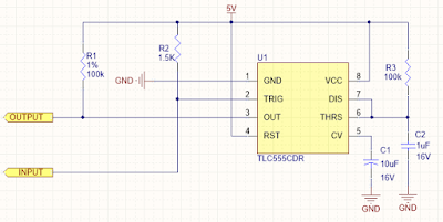
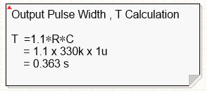
Pulse Width Stretcher using 555 Timer IC


This circuit will invert and stretch the short period active low input signal as below.


Required pulse width can be calculated by using this equation.


Ultra-Precise, Current-Sense Amplifier

   This ultra-precise current sense amplifier that can measure voltage drops across shunt resistor, R1 over a wide common mode range from 2....