Showing posts with label IO Protection. Show all posts

Monday, June 10, 2024

Over Current Protection at Output Stage/ Pins


This circuit helps to limit the output current less than 20mA which can be sense and set by R1 & R8. It also disconnects I/O when the output shorts to positive high voltage or negative high voltage by limiting the current.

The diode, D1at the output and 5V0 pin is used to suppress the kick-back voltage from an inductive load that is excited when the drivers are turned off (stop sinking) and the stored energy in the coils causes a reverse current to flow into the coil supply through the kick-back diode

Friday, June 7, 2024

Overvoltage Protection


This circuit monitor VIN and protect the output voltage by a series connected transistor Q14. During over voltage condition Q14 B is turn on which cause Q14A to disconnect output to VIN. Desired overvoltage limit is set by D10 plus VBE of Q14. For example, if the required cutout voltage is 12V, Zener voltage of D10 has to be 12-0.6= 11.4 V.


Monday, May 16, 2022

CAN-BUS Termination and Protection

 A properly terminated CAN bus is terminated at each end with the characteristic impedance of the cable, this is typically 120Ω on each end for a 60Ω load on the CAN driver. The 60Ω–60Ω split termination is preferred to reduce high-frequency noise and common-mode drift. Usually, 60R resistor is not cost effective and a choice of 60.4R with 1% tolerance is better.


If we are using CAN-BUS for long distance for more than 50m, it is advised to reduce the bitrate to minimize an errors and signal distortions.

The maximum possible CAN Bitrate depends on the total CAN bus cable length: 

- 1 Mbit/s: max. 40 m

- 500 kBit/s: max. 100 m

- 125 kBit/s: max. 500 m  

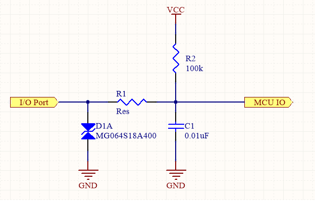
To enhance CAN Bus reliability, communication BUS varistor can be added near next to the connectors.

If the device is intended to be used in harsh environment and required isolation due to ground potential difference between subsystems, Galvanic isolation barrier can be placed between CAN BUS transceiver and MCU. It is also important to use isolated DC-DC power supply for transceiver.

Monday, April 9, 2018

Micro-controller Output Protection by Current Limiting

Q1B is the pass or output transistor. R2 sense the output current. Q1A  is the protection transistor which turns on as soon as the voltage across R2 becomes about 0.65 V.
Maximum current = VBE,Q1A / R2 = 0.65 / 33 = 19.7 mA

Thursday, April 5, 2018

Protecting microcontroller's Inputs

1) Filtering


This circuit can be used to protect I/Os of micro-controller/ processors.  D1A is used for Transient Voltage Suppression or ESD protection. R1 acts as current limiting resister as well as low pass filter together with C1. The value of the resistor and the capacitor must be sized so that the micro-controller does not miss any signals.

Rise time of the fastest income edge = 2.2 RC

2) Limiting Current


This circuit limit the input current to 23.2 mA (VZ/R1 = 5.1 / 220).

3) Limiting Voltage

Use schottky diodes with 0.2 Vf for better performance. Once the voltage at I/O pin is greater than VCC by about 0.2V, the top diode will start to conduct. The bottom diode will conduct for voltage less than -0.2V.

Saturday, May 28, 2016

Short Circuit Monitoring

Comparator Circuit for Open/Short Detection


At open circuit condition across +/- of the input connector, V- will get around 5.1V. Since V- (5.1V) is greater than V+ (2.5V), output to the microcontroller will be Low (0V).

When the short circuit is detected across +/- of the input, V- will get less than 2.5V which will make the output to go High (5V).

This circuit can be used for simple continuity test circuit by connecting LED and Buzzer at the output. 

Ultra-Precise, Current-Sense Amplifier

   This ultra-precise current sense amplifier that can measure voltage drops across shunt resistor, R1 over a wide common mode range from 2....