Showing posts with label embedded systems development. Show all posts

Friday, March 20, 2020

Digital filtering technique , ADC Filter


A digital filter system usually consists of an analog-to-digital converter (ADC) to sample the input signal, followed by a microprocessor and some peripheral components such as memory to store data and filter coefficients etc.
Program Instructions (software) running on the microprocessor implement the digital filter by performing the necessary mathematical operations on the numbers received from the ADC.

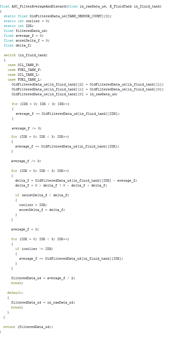
Here is a simple digital filter which identifies and reject transient response signal. It basically returns average of best two samples of the last three. The third sample is discarded.

Algorithm:
1. Calculate the average of the last 3 samples
2. Identity the sample furthest from the mean value (which is the outlier)
3. Discard the outlier and average the remaining two samples
4. Returns float value of the averaged data (y(i)).


Monday, April 9, 2018

Micro-controller Output Protection by Current Limiting

Q1B is the pass or output transistor. R2 sense the output current. Q1A  is the protection transistor which turns on as soon as the voltage across R2 becomes about 0.65 V.
Maximum current = VBE,Q1A / R2 = 0.65 / 33 = 19.7 mA

Sunday, April 8, 2018

High Voltage Monitoring/ Measuring using Microcontroller's ADC input


Voltage divider resistor network is used to step monitored voltage down to the range as necessary  for A/D conversion. Passive low-pass filter is used for noise rejection.

Wednesday, June 1, 2016

Embedded C Programming For PIC Chips

C Programming Using CCS Compiler For PIC Microcontrollers

Here is a link for good tutorial of programming PIC microcontroller in C.

http://harfordhackerspace.org/2010/02/programming-pic-microcontrollers-in-c/

Motor Control using Pulse-Width Modulation (PWM)


In this program, a jumper on Port B directly selects the PWM output. PWM output is only present if a jumper to ground is present on one the least significant 3 bits of port B.


The program demonstrates the use of control registers to effect PWM operation.  One thing to notice is the fact that the program waits for a change on the input pins before selecting a new pulse-width duty cycle and reloading CCPR1.

Ultra-Precise, Current-Sense Amplifier

   This ultra-precise current sense amplifier that can measure voltage drops across shunt resistor, R1 over a wide common mode range from 2....