Monday, December 3, 2018
Friday, November 23, 2018
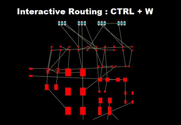
Altium Designer: Useful Shortcuts for Component Placement
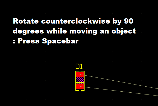
- Rotate counterclockwise by 90 degrees while moving an object : SPACEBAR
- Align selected objects by top edges : SHIFT + CTRL + T
- Distribute selected objects equally in horizontal plane : SHIFT + CTRL + H
- Align selected objects by left edges : SHIFT + CTRL + L
- Align selected objects by right edges : SHIFT + CTRL + R
- Distribute selected objects equally in vertical plane : SHIFT + CTRL + V
- Align selected objects to grid : SHIFT + CTRL + D
- Align selected objects by bottom edges : SHIFT + CTRL + B
Thursday, November 22, 2018
Altium Designer : Pcb Panelization
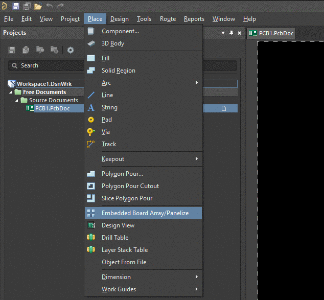
On the Place tab, Select Embedded Board Array/ Panelize. Click anywhere in the PCB area. Under Properties menu, select your PCB and set desired Column margin and Row spacing.
Altium Designer : Creating Board Outline From Mechanical Outline and Making Cutout Holes
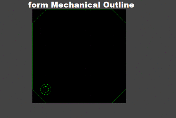
Select Mechanical Outline. Under Properties menu, Change Mechanical outline layer to user defined board outline layer.
To create custom board shape, select board outline that has been created. On the Design Tab, in the board shape, select Define from selected Objects.
To create a cutout hole, select the desired outline. On the Tool Tab, in the Convert, select Create Boardcutout from selected primitives.
Altium Designer : Moving Design Origin to User's Preferred Location
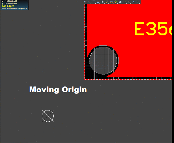
On the Edit tap, in the Origin, choose Set.
Altium Designer, Shortcuts for Viewing, Changing Grid and Snap Setting

Toggle measurement Unit : Q
Accessing Grid menu : G
Changing snap setting : SHIFT + E
Switching 2D and 3 D View : 2 & 3
Fit all objects into view : CTRL + PAGE DOWN
Zoom in around cursor (zooms around cursor, position the cursor first) : CTRL + Mouse-wheel up (or PAGE UP)
Zoom out : CTRL + Mouse-wheel down (or PAGE DOWN)
Wednesday, November 21, 2018
AAA Battery Protection with Wrong Polarity LED Indicator

Thursday, June 7, 2018
A Basic Transistor Amplifier with self-bias
Wednesday, June 6, 2018
Common Mode and Differential Mode Filters to limit EMI Issues

Thursday, May 24, 2018
Simple Logic Gates using Diodes

Diodes can be used for implementing simple logic gates such as AND or OR combinations. For AND gate, all inputs must be tie to high, 5V for the output logic high. For OR gate, the output is high if any input(s) are high.
Thursday, May 10, 2018
Emergency Phone Charger From 3 x AA Battery with output Protection

Three AA batteries (3 x 1.5V) is using as emergency power source for mobile device or phone charging. Output current is limited to 0.5A and protected from out short circuit or high current drawn from the batteries.
Subscribe to:
Posts (Atom)
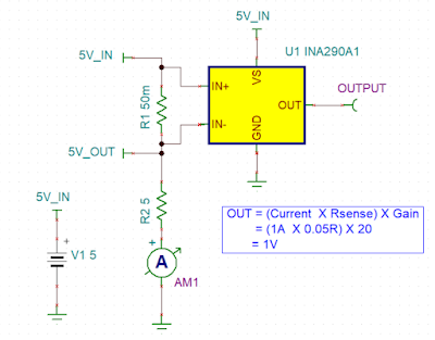
Ultra-Precise, Current-Sense Amplifier
This ultra-precise current sense amplifier that can measure voltage drops across shunt resistor, R1 over a wide common mode range from 2....
-
 Voltage divider resistor network is used to step monitored voltage down to the range as necessary for A/D conversion. Passive low-pass f...
 -
 Import Changes from Schematics to PCB in Alitum as below. 1) Compile the Project 2) Design >> Import Changes From XXX.PrjPCB 3)Execut...