When the input is below 18 V, Q1 is OFF state allowing C3 to be charged though R3. Thus turning on Q105. Once the input voltage exceed 18 plus two diode drop Volts, Q1 will turn on that discharge C3 and Q105 is OFF.
Once the input goes back below 18 V, Q1 is turn off again. This allows C3 to be charged slowly resulting soft-start at the output.
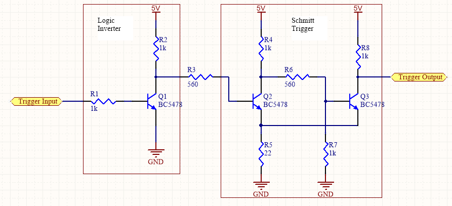
Q1B is the pass or output transistor. R2 sense the output current. Q1A is the protection transistor which turns on as soon as the voltage across R2 becomes about 0.65 V.
Maximum current = VBE,Q1A / R2 = 0.65 / 33 = 19.7 mA
Voltage divider resistor network is used to step monitored voltage down to the range as necessary for A/D conversion. Passive low-pass filter is used for noise rejection.
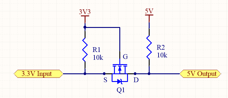
VGS (th) , Gate Source threshold voltage = -2.0 V
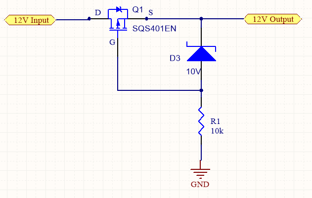
Zener Voltage = 10 V, Q1-VGS max = +/- 20V
Zener diode, D3 will protect the gate from excessive voltages/ unwanted spikes
By
referring the Gate signal to the ground line, the device is fully turned on when the
battery is applied in the right polarity. For the first start up, the intrinsic body diode
of the MOSFET will conduct, until the channel is switched on in parallel. The Zener
diode will clamp the Gate of the MOSFET to its Zener voltage and protecting it
against overvoltage.
By reverse polarity, the MOSFET will be switched off, because the Gate Source
voltage for this case will be positive (voltage drop over the Zener diode).
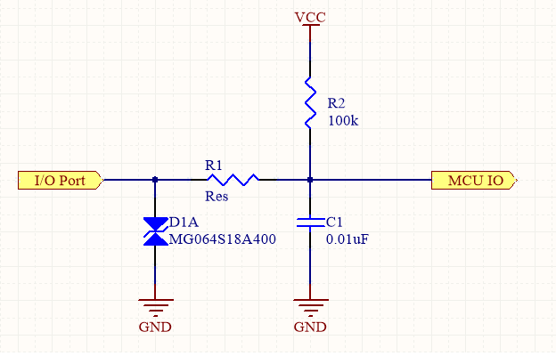
This circuit can be used to protect I/Os of micro-controller/ processors. D1A is used for Transient Voltage Suppression or ESD protection. R1 acts as current limiting resister as well as low pass filter together with C1. The value of the resistor and the capacitor must be sized so that the micro-controller does not miss any signals.
Rise time of the fastest income edge = 2.2 RC
2) Limiting Current
This circuit limit the input current to 23.2 mA (VZ/R1 = 5.1 / 220).
3) Limiting Voltage
Use schottky diodes with 0.2 Vf for better performance. Once the voltage at I/O pin is greater than VCC by about 0.2V, the top diode will start to conduct. The bottom diode will conduct for voltage less than -0.2V.
In this program, a jumper on Port B directly selects the PWM output. PWM output is only present if a jumper to ground is present on one the least significant 3 bits of port B.
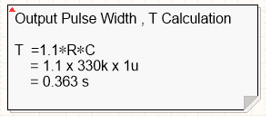
The program demonstrates the use of control registers to effect PWM operation. One thing to notice is the fact that the program waits for a change on the input pins before selecting a new pulse-width duty cycle and reloading CCPR1.