
Saturday, April 7, 2018
Voltage Doubler Circuit
Reverse Polarity Protection
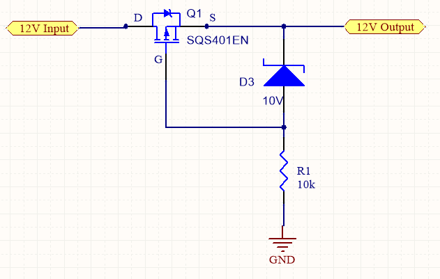
Zener Voltage = 10 V, Q1-VGS max = +/- 20V
Zener diode, D3 will protect the gate from excessive voltages/ unwanted spikes
By
referring the Gate signal to the ground line, the device is fully turned on when the
battery is applied in the right polarity. For the first start up, the intrinsic body diode
of the MOSFET will conduct, until the channel is switched on in parallel. The Zener
diode will clamp the Gate of the MOSFET to its Zener voltage and protecting it
against overvoltage.
By reverse polarity, the MOSFET will be switched off, because the Gate Source
voltage for this case will be positive (voltage drop over the Zener diode).
Friday, April 6, 2018
Logic Input/ Push Button input Buffer Circuit

This circuit squares up and debounces a push button or logic input signal.
Bi-directional Logic Level Shifter
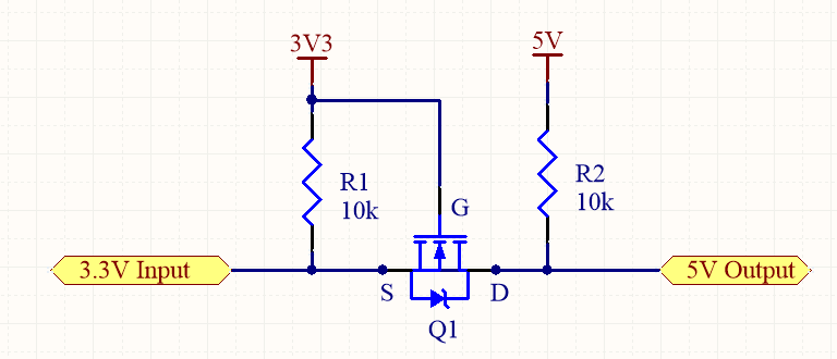
Input = 0V ; VGS > VGS(th) ; FET = ON ; Output = 0V
Input = 3.3V ; VGS < VGS(th) ; FET = OFF ; Output = 5V
Thursday, April 5, 2018
Protecting microcontroller's Inputs
1) Filtering
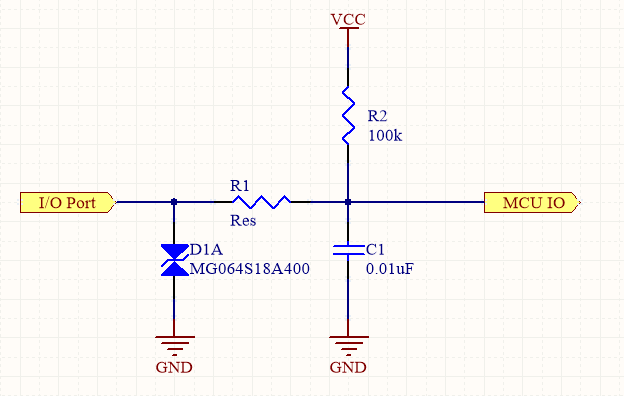
This circuit can be used to protect I/Os of micro-controller/ processors. D1A is used for Transient Voltage Suppression or ESD protection. R1 acts as current limiting resister as well as low pass filter together with C1. The value of the resistor and the capacitor must be sized so that the micro-controller does not miss any signals.
Rise time of the fastest income edge = 2.2 RC
2) Limiting Current

This circuit limit the input current to 23.2 mA (VZ/R1 = 5.1 / 220).
3) Limiting Voltage

Use schottky diodes with 0.2 Vf for better performance. Once the voltage at I/O pin is greater than VCC by about 0.2V, the top diode will start to conduct. The bottom diode will conduct for voltage less than -0.2V.
Wednesday, June 1, 2016
Embedded C Programming For PIC Chips
C Programming Using CCS Compiler For PIC Microcontrollers
Here is a link for good tutorial of programming PIC microcontroller in C.
http://harfordhackerspace.org/2010/02/programming-pic-microcontrollers-in-c/
Motor Control using Pulse-Width Modulation (PWM)

In this program, a jumper on Port B directly selects the PWM output. PWM output is only present if a jumper to ground is present on one the least significant 3 bits of port B.

The program demonstrates the use of control registers to effect PWM operation. One thing to notice is the fact that the program waits for a change on the input pins before selecting a new pulse-width duty cycle and reloading CCPR1.
Tuesday, May 31, 2016
PCB Know How
Generic
Standard on PCB Design (IPC2221A)
PCB
Rigid Laminate material (FR4, typically) consisting of
a glass epoxy substrate clad with copper on two sides for double sides (0.062”
typically)
PCB
fabrication Gerber data requirement
1 1) Top
Electric (Art work)
2 2) Botton
Electric (Art work)
3 3) Top
Slilk (Art work)
4 4) Top
Resist (Art work)
5 5) Plated
Through Hole (N.C Drill)
6 6) Non-Plated
Through Hole (N.C Drill)
7 7) Board
Outline (Art work)
8 8) Drill
Table
Electrical Isolation (Creepage Vs Clearance)
Electrical
Clearance
AC and pulsed voltage > 200V must consider
dielectric and capacitive effect of substrate in addition to spacing.
Minimum spacing requirement according to withstand
voltage are as below
|
Withstand
Voltage (V)
|
Minimum
Spacing (mil)
|
|
0 ~ 30
|
3.9
|
|
31 ~ 150
|
24.0
|
|
151 ~ 300
|
49.2
|
|
301 ~ 500
|
98.4
|
Electrical Isolation (Creepage Vs Clearance)
Creepage is the shortest path between two conductive
parts measured along the surface of the insulation. Clearance is the shortest distance between tow
conductive parts measured through air.
Copper Weight
1 oz of copper will cover one square foot area when
rolled out to a thichness of 0.0014 inch or 1.4 mil.
|
Copper
Weight (oz)
|
Thickness
(inch)
|
|
½
|
0.0007
|
|
1
|
0.0012 ~ 0.0014
|
|
2
|
0.0028
|
PCB Surface Finishing
Different types of PCB finishing are as below
1) Hot
Air Solder Level (HAL or HASL)
2) Hard
Gold-Electro plated gold
3) Electro
Less Nickel Emersion gold
4) White
Tin
5) Organic
Solderable Preservative (OSP)
The most common surface finishing we can see is Hot
Air Solder Leveling. In this process, Panels are processed through a bath of
molten solder, conversing all exposed metal surfaces. High pressure hot air,
directed at both sides of the panel simultaneously, removes excess solder from
the holes and surfaces.
PCB Trace Width vs. Current Table
A PCB trace width vs. current table helps you understand the relationship between PCB trace width and current carrying capacity so you can determine the required trace width for your printed circuit board design.

Monday, May 30, 2016
Microphone Pre-amp

R1, R2, R3,
R4 & R8 : Low excess noise metal Film
C1, C2
& C3 : Input and output coupling
C4 : Noise
filter, C5: by pass
NOTE: Input
Cable to microphone must be shielded
Sunday, May 29, 2016
Relay Circuits
Momentary Relay Activation Circuit


Relay will energize
momentarily until the capacitor is fully (or partially) charged.

Relay coil produce brief
high voltage spikes when they are switch off and this can destroy transistors
and ICs in the circuit. To prevent damage, a protection diode must be placed
across the relay.
Controlling Multiple LEDs
Multiple LED Control Using Minimum I/O pins

Truth table for controlling six LEDs using three I/O are as shown below:

H = Output Set high (5V)

Truth table for controlling six LEDs using three I/O are as shown below:

H = Output Set high (5V)
L = Output set low (ground)
I = Input
More LEDs can be controlled by using this equation:
Numbers of LEDs = (Numbers of PINs) x ( Numbers
of PINs – 1)
For example:
Number of LEDs = 4 x (4-1)
= 4 x 3
= 12 LEDs
Speaker Volume Control Circuits
Speaker Circuit with Adjustable Volume Control

This is how we usually built 8/4/16 Ohm speaker with adjustable Volume Control. It can handle up to 15W speaker without any issues.
100V Line Audio Volume Control with bypass Option
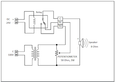
This is 100V line speaker volume control with Emergency bypass. It requires DC 24V to bypass the audio level control.
Subscribe to:
Posts (Atom)
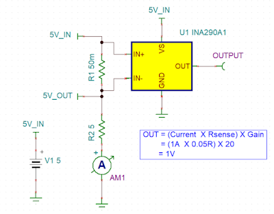
Ultra-Precise, Current-Sense Amplifier
This ultra-precise current sense amplifier that can measure voltage drops across shunt resistor, R1 over a wide common mode range from 2....
-
 Voltage divider resistor network is used to step monitored voltage down to the range as necessary for A/D conversion. Passive low-pass f...
 -
 Import Changes from Schematics to PCB in Alitum as below. 1) Compile the Project 2) Design >> Import Changes From XXX.PrjPCB 3)Execut...